I'd like to share just another idea of how to modify the Panasonic DMW-DCC8. Inspired by this thread and a thread next door as well as encouraged by @feha's tutorial I started my modification.
My post is divided in two parts: Part 1 is about the concept. Part 2 is about the implementation.
Part 1: Concept
I will try to give you a straight forward description of my doing but it actually was a very iterative process with countless loops.
My goals have been the following ones:
- build an adapter which can be used with almost every battery, preferably one of those Lithium-Polymer-Batteries for RC Cars, Helicopters & Co. - adapter must deliver the same voltage which is delivered by the original adapter in combination with the original power supply - usage of a highly flexible cable to be able to get small bending radii and to unload the adapter and therefor the camera when mounted on a support rig - modification of high quality and durability, it must look nice and you don't have to care about it in everyday life
I picked up the idea to integrate a step-down converter right into the adapter (http://forums.planet5d.com/threads/119993-Panasonic-DMC-GH2-Power-Mod).
I've decided to start with the original coupler by Panasonic because it has this little circuit board with two resistors inside. I've got no idea what these resistors are for, but I thought it's better to keep their functionality. The original coupler is also a good starting point for the housing because it is basically an empty case.
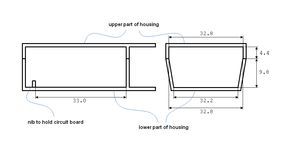
Then I searched the web for a step-down converter which is small enough to fit into the housing. Later I saw that Vitaly has already found the same small converter (http://www.personal-view.com/talks/discussion/3957/voltage-step-down-module/p1). The dimension is declared with 33 mm x 33 mm x 12 mm. But is it small enough? Unfortunately not! The adapter housing is 32.2 mm wide inside at the narrowest position. Damn! But if you look at the pictures of the step-down converter there is still a little bit room for reducing the size of the circuit board without damaging the electrical parts on the board, hopefully. The hight should be enough even if the 12 mm out of the converter description don't include the pins for soldering. I gave it a try and ordered such a converter. The exact dimension of the converter turned out to be 33.2 mm x 33.2 mm x 15.4 mm (from top of potentiometer to bottom of pins for soldering) and may vary from item to item. So it's going to be hard to integrate this circuit board into the adapter housing. Even the height is critical. See picture “adapter inner dimension.png” for the inner dimensions of the adapter housing (not to scale).
The heart of the converter is an integrated circuit named LM2596. See file “LM2596.PDF” for some detailed technical data.
http://www.personal-view.com/talks/uploads/FileUpload/f8/47378121919f6f9071d8077e27af68.pdf
A lot of discussions existing about the efficiency of such a converter. You should have a look into the data sheet on page 4. There is a nice chart called “Efficiency”. This chart is measured based on a layout shown on page 7. I can't recognize if the converter which I have chosen has the same layout. But I guess there is not much difference. Interestingly the efficiency goes up with higher input voltages up to around 25 V. So if you go like me with a Lithium-Polymer-Battery pick up rather a 5S-LIPO than a 3S-LIPO even if the minimum voltage of a 3S-LIPO is still around 1 V above the voltage we need (when you shut off at 3.3 V per cell), see also chart called “Dropout Voltage” on page 4.
To make sure that the converter becomes not a heater just a rough consideration: The GH2 average power consumption is about 3.4 W at 8.4 V according to the manual which means it draws about 400 mA. This current draw could be validated by the guys at dvxuser. Additionally it was measured by the guys at dvxuser that the GH2 draws up to around 800 mA in some situations for a short time (camera turn on, after using flash light). That means for me that the converter is perfectly designed for this application and that there is no risk of overheating because this little piece is designed for up to 3 A.
The maximum current is also the key data to find the right wires / cable. I've used two approaches to calculate the minimum wire cross-section:
1) Current density
The maximum current density for copper is estimated with 4-6 A/mm2 (empirical or practical value I guess). The formula to calculate the cross-section is: cross-section = current intensity / current density. For this application it means: 0.8 A / 5 A/mm2 = 0.16 mm2.
2) Voltage drop
The maximum voltage drop should be small and is generally considered with 3-5 %. But that is too much! 5 % of 8.8 V is 0.44 V. The voltage would drop below 8.4 V and the camera will display the message “This battery cannot be used”. By the way, 8.8 V is the measured output of the original Panasonic power supply for the original Panasonic DC coupler. The voltage may drop from 8.8 V to 8.4 V. That is about 4.5 % voltage drop. Let's take 1% and the following formula to calculate the cross-section: cross-section = (current intensity x specific resistance of copper x 2 x length of wire) / voltage drop. For this application it means: (0.8 A x 0.0172 Ω mm2 / m x 2 x 0.05 m) / 0.086 V = 0.016 mm2. So the voltage drop is no issue because the wires are just too short.
At the end I've decided to use a wire with a cross-section of 0.25 mm2! The wires of the original Panasonic adapter are rated AWG20 = 0.5 mm2. But I think the decision for 0.5 mm2 was not only driven by the current intensity but also by the cable thickness. It's a dual cable which means it's a cable with two wires without an additional cable coating. If Panasonic would have chosen a 0.25 mm2 wire then the cable would be simply too tiny to withstand everyday life.
Now I had to look for a cable which has two 0.25 mm2 wires. I've found a cable, see bill of material in part two. And the coating of this cable is PVC which means it is highly flexible. It almost feels like rubber or silicon cable coating. The outer diameter is 3.9 mm. Finding the right plug was quite easy, see bill of material in part two. The plug is rated for 4 A. Enough! And the sleeve support has a diameter of 4.0 mm. So the selected cable fits perfectly into the cable sleeve.
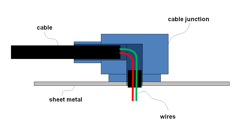
The most difficult part was to find a solution to attach the cable on the adapter housing. There is already a big hole in the adapter housing. Much too big for a cable with 4 mm outer diameter. My first idea was to use a grommet to fill the hole nicely. But there is no space. To solve this problem I desoldered the sockets from the step-down converter. Then the next problem. How to secure the cable so it does not become loose or even worse the wires tear off the circuit board when you pull accidentally on the cable? I developed several ideas with a clamp, with glue and with shrink tubings but nothing met my goal of high quality. Finally I decided to design my own parts, see picture of concept drawing “sheet metal and cable junction.png”. This solution basically consists of a sheet metal and a specially designed cable junction. The sheet metal will be placed inside the adapter housing similar to the circuit board. And the cable junction will be the bridge between the inside and the outside of the adapter. With this cable junction I'm able to bend my cable by 90 degrees in a small area because inside this cable junction only the two little wires are routed without the cable coating.
Part 2 Implementation
First find the bill of material with links to the manufacturers. Second the bill of material as a picture, see picture “bill of material.jpg”
Housing: Panasonic DMW-DDC8 (http://panasonic.net/avc/lumix/systemcamera/gms/gh2/optional_accessories.html#acc06)
DC-Converter: Step-Down-Converter based on LM2596 (unknown chinese manufacturer)
Cable: Kabeltronik LifYY 2×0.25 mm2 (http://www.kabeltronik.de/electronics-industry/control-cables-unshielded/control-cable-extremely-flexible-lifyy)
Plug: Lumberg 1634 02 (http://lumberg.de/main/common/produkt_fs.asp?lang=eng&produktname=1634_02)
Bracket: self-made (see drawings)

Next the steps to bring everything together:
You can open the DC coupler by just pressing carefully but with a good amount of pressure the cutter between both parts of the housing. Both parts are glued together. It sounds like something breaks but except the glued areas (which actually really breaks) the housing stays undamaged. See picture “cutter.jpg”

You have to remove all stringer inside to make room for the step-down converter. Don't remove the little nibs which hold the circuit board. I processed the housing with my Dremel. A lot of handwork and it does not look very professional, but it's inside the housing. See picture “housing.jpg”

You have to use abrasive paper to trim the size of the step-down converter. Just move the circuit board back and forth on the paper and make sure to evenly remove the material of the board. You have to remove almost 0.5mm on every side until it fits into the housing (the idea with sheet metal and the cable junction also requires some space for the sheet metal inside the adapter housing). Be careful because almost all the components are soldered on top of the board. Additionally I removed the sockets as already mentioned in part one. And I have sanded very carefully some millimeters off of the pins beneath the board with my Dremel. See picture “resize step-down converter.jpg”

The circuit board of the step-down converter, the original little circuit board out of the adapter and the sheet metal now fits into the housing and i can close the housing without exertion. See picture “assembly.jpg”

In the picture above you can already see the sheet metal with the cable junction. In the picture below you can see it fully assembled. I have glued all together with a two component epoxy resin adhesive. The cable junction is made out of PVC. Don't use other plastic like POM which can be machined very good but you will have problems while glueing. The sheet metal is made out of stainless steel. Both can be glued together very well with a two component epoxy resin adhesive. I stripped the outer cable coating and kept 3 mm of this outer cable coating to put it back on the wires from the other side, see second picture below. I have attached some more pictures to give you a better idea of what I have done, see pictures “cable1.jpg”, “cable2.jpg” and “cable3.jpg”


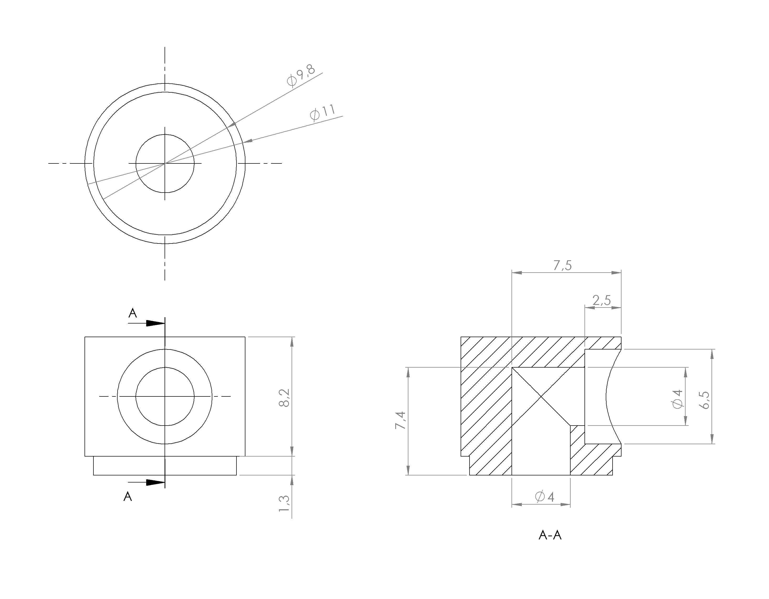
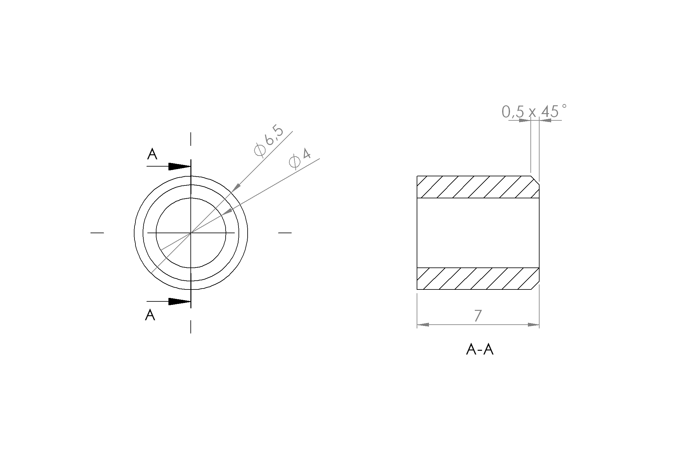
And here find the drawings of at least the cable junction, see pictures “drawing1.png” and “drawing2.png I have no drawings of the sheet metal because it is made by hand freestyle. The material is as mentioned PVC-U. I've defined no production tolerances. Just make it as accurate as possible and make sure the two parts fit together. But one hint: Don't go under 1.3 mm of hight of the lower ring. For me it was absolute the minimum!
The last thing to do is to solder everything together. The cables go across each other because the input of the step-down converter is located to the opposite of the housing opening. That's because otherwise the cable from the little circuit board with the two resistors out of the original adapter would be located directly behind the potentiometer (the blue box with the screw on top). That is not working. And to be honest. It's much easy to solder a cable that is about 3 cm long than a cable that is just 0.5 cm long. Don't wonder that the plug is not yet screwed together. I want to wait until I put everything on my support rig. Maybe I can further shorten the cable. see picture “final assembly.jpg”

The most important thing (and I have expected nothing more than that due to the fabulous spadework of a lot of other people): It works and my GH2 is still alive, see picture “GH2 attached to LIPO.JPG”

Hopefully it is interesting and helpfull for you guys!
First of all I am talking about naked Lithium-Polymer-Batteries used for RC Cars & Co. and not about the Battery-Packs you can buy to power your mobile devices! Second with my explanations I have always the idea of powering the GH2 with a battery via a converter in mind!
The basic discharge characteristic of a LIPO primary cell looks like this example, see chart „Discharge rate characteristics“ in file „data sheet primary cell.pdf“.
http://personal-view.com/talks/uploads/FileUpload/fe/9e846951088088dfedb402114dff0d.pdf
A primary cell can provide fully loaded 4.2 V and fully discharged around 3.0 V. With the application of powering the GH2 with a big LIPO you have rather small discharge currents. That means a flat curve over time with a steep end. Often it is suggested to cut off a cell between 3.3 V and 3.6 V and not at 3.0 V. That makes sense to me because it is better for the battery to not be fully discharged and the discharge curve is so steep at the end, that it can take only seconds to over discharge your battery.
When you put more primary cells in series together then you get higher voltages. That means for one up to four cells you get the following voltage ranges:
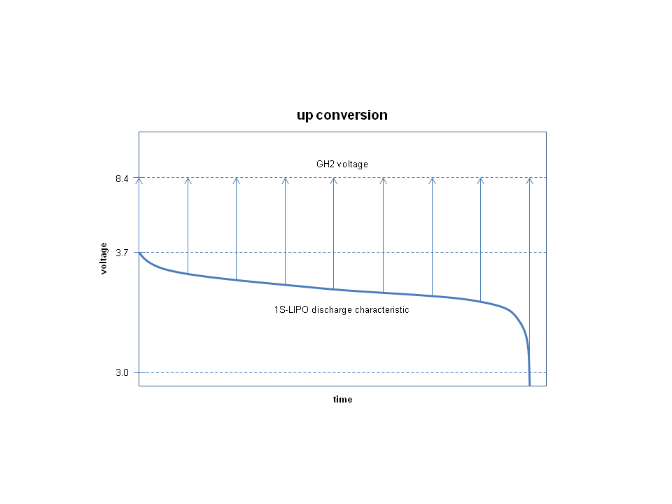
1S: 3.0 V up to 4.2 V with nominal voltage of 3.7 V
2S: 6.0 V up to 8.4 V with nominal voltage of 7.4 V
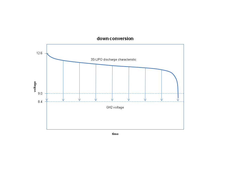
3S: 9.0 V up to 12.6 V with nominal voltage of 11.1 V
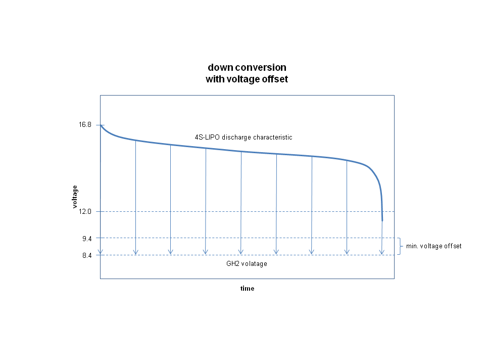
4S: 12.0 V up to 16.8 V with nominal voltage of 14.8 V
To power the GH2 you need between 8.4 V and 8.8 V. 8.8 V has been measured as output voltage of the original Panasonic power supply. Below 8.4 V we get an error message from the camera and above 8.8 V I don’t know what will happen.
How to get a voltage between 8.4 V and 8.8 V? The first option is to always convert from higher voltage down. The second option is to always convert from lower voltage up. And the third option is a combination of both conversions. The charts below show an up and a down conversion (simplified and not to scale), see pictures “down conversion.png” and “up conversion.png”.
The next chart tries to show the effect that @Mike_C has observed (simplified and not to scale), see picture “combi-conversion.png”.
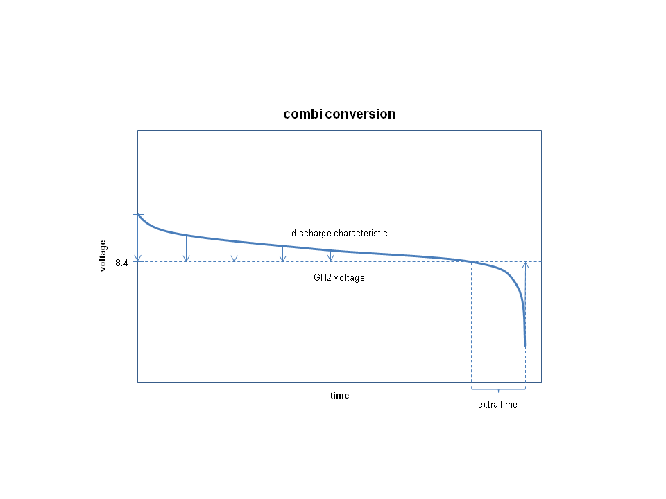
You can clearly see the extra time which an additional step-up-converter stage will bring. Without it the camera would turn off before all the energy of the battery has been used. But as I mentioned before I would not prefer this approach. I don‘t know if the current of the battery has to pass always both converter stages or if the unnecessary stage is bypassed. But if the current has to pass both stages the efficiency gets worse. Let’s assume a converter stage has 0.85 efficiency. With two stages you get 0.85 x 0.85 = 0.7225 efficiency. Not good! So even if you gain some extra time a lot of your energy goes into heat due to several converter stages! Better is to make sure you have only one converter stage. But then your battery needs to be bigger which means provide a higher voltage. If you use a Battery-Pack whose nominal output voltages are different to 3.7 V, 7.4 V, 11.1 V or 14.8 V or in general multiples of 3.7 V I am quite sure that there is another converter inside the Battery-Pack to deliver voltages like 12 V, 9 V and 5 V.
But in reality things often get more complicated. The converter needs a little bit more input voltage than it outputs, see the data sheet of the LM2596, page 4, chart „Dropout Voltage“ which you can find right here http://personal-view.com/talks/discussion/comment/116764#Comment_116764 That means you need additionally about 1 V if you use your own converter. In total your battery must provide at least 9.4 V up to 9.8 V. The last chart illustrates this fact, see picture „down conversion with voltage offset.png“.
I have chosen a 5S-LIPO because I also want to power an external field monitor which needs at least 12 V. A 4S-LIPO would do the job. But due to the fact that the efficiency of the LM2596 is better with higher voltages and because I wanted even more energy I decided to use a 5S-LIPO. Assumed that a primary cell has 5 Ah then I get 3.7 V/cell x 5 Ah/cell x 5 cells = 92.5 Wh instead of 3.7 V/cell x 5 Ah/cell x 4 cells = 74.0 Wh. But you have to check what your LIPO supplier can offer. You can play with the number of primary cells and with the capacity of a primary cell to determine your overall battery energy.
All this applies only if you use a LIPO for RC Cars & Co.! I don't want to conceal the big disadvantage of this solution: It's about the Battery-Management-System. With this solution you also have to take care not to over charge and over discharge your battery. This problem is not existent with Battery-Packs for mobile devices because all the electronic controls are already inside the Battery-Pack. Just load it. Just use it. With a LIPO for RC Cars & Co. you need a charger with a so called balancing feature and at least a so called LIPO saver which indicates your battery is empty. The advantage of this solution is of course the high efficiency which can be translated in longer run-times and the opportunity to design your battery-system according to your needs.